- Home
- Cart
- Browse Products
- Catalogues
- Albin Group
- Arco Marine
- Athena
- BEP Marine
- Bob's Machine Shop
- CDI Electronics
- Champion Spark Plugs
- Evinrude Accessories
- GB Remanufacturing
- JB Weld
- Jaltest Diagnostics
- Kicker Audio
- Martyr Anodes
- Mercury Accessories
- NGK Spark Plugs
- Narva Marine
- Shields Fuel Hose
- Solas Propellers
- Suzuki Accessories
- Volvo/Yanmar Parts (CROM)
- Wiseco Pistons
- Technical Resources
- Parts Diagrams
- Product Information
- Promotions
- PROMT News
- Prop Finder
- Video Library
- About Us
- Contact Us
- Find Us on Social
NMEA2000 FUNDAMENTALS
INTRODUCTION
 The National Marine Electronics Association, is a worldwide, member-based trade organization revolving around marine electronics interface standards
NMEA2000, also known as NMEA 2000 or N2K, is a plug-and-play communication standard used to connect various marine electronic devices on a boat. This standard was developed to enable the rapid integration of marine electronics, devices, and CAN bus-enabled engines to coexist coherently on a single network, sharing data and information seamlessly.
Every electronics manufacturer must register with NMEA, and each device produced needs to be registered with NMEA as well. These devices must be designed, manufactured, and built to strict guidelines provided by NMEA. Additionally, each device must undergo thorough testing on the NMEA2000 CAN BUS network to prove compliance with the stringent requirements of the NMEA2000 network protocol to receive the NMEA2000 certificate.
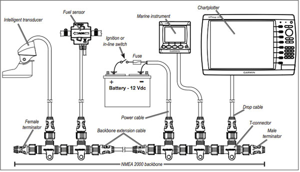
Basic NMEA2000 Network:
NMEA 2000 CAN Message
NMEA 2000 is a communication standard used in the marine industry to connect various electronic devices like engines, instruments, and sensors. It's built on the Controller Area Network (CAN) bus, a robust communication protocol used in many industries.
How it works:
- Electrical Signal: Data is transmitted as an electrical signal over two wires, CAN High and CAN Low.
- Differential Voltage: The system uses differential voltage, meaning the data is encoded in the difference between the two wires. This makes it less susceptible to noise and interference.
- Bus Speed: The bus speed is typically 250 kilobits per second, allowing for a high rate of data transfer.
- Message Structure: Data is sent in packets called frames. Each frame contains information about the sender, receiver, and data content.
Importance of Termination:
- Signal Integrity: Proper termination is crucial for maintaining the correct voltage levels on the CAN bus.
- Reflections: Without proper termination, signal reflections can occur, causing errors and data corruption.
- Bus Performance: Termination ensures optimal bus performance and reliable communication.
Network Issues:
- Short Circuits: A short circuit between CAN High and ground, CAN Low and ground, or CAN High and CAN Low can severely disrupt the network.
- Intermittent Issues: Corrosion in connectors can lead to intermittent short circuits or increased resistance, causing unstable communication.
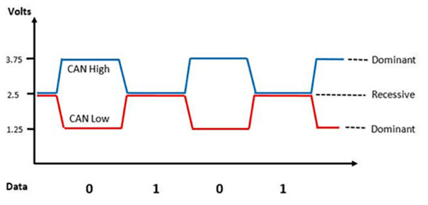
CAN Bus Messages Visualised:
The below image visualises how data is sent over the CAN bus. The devices on the network interpret the differential in voltage a binary 0 or 1 and stings the values together to make up the entire message. Termination, voltage drop, and poor connections can affect the voltage in the wire which will impact the CAN Bus performance.
NMEA2000 Can Message:
NMEA 2000 Terminology:
- CAN BUS: Controller Area Network (CAN) bus is a vehicle bus standard for connecting and communicating between various electronic control units (ECUs). NMEA 2000 uses CAN bus as its underlying communication protocol.
- CAN Messages: These are packets of data transmitted over the CAN bus. They contain information about specific data parameters, such as speed, depth, or engine RPM.
- Instance: An instance is a specific occurrence or realization of a data parameter. For example, a speed sensor might have multiple instances, such as "boat speed" and "wind speed." So each device would have a different instance so displays can identify the data from each device and correctly assign its value to the correct data field.
- Device ID: A unique identifier assigned to each device on the NMEA 2000 network. It's used to address devices and route messages.
- Device address: Similar to Device ID but often refers to a specific address on the network.
Network Characteristics:
- LEN (Load Equivalency Number): A measure of a device's current draw on the NMEA 2000 network. 1 LEN equals approximately 50 milliamps.
- Voltage Drop: The decrease in voltage as electrical current flows through the NMEA 2000 backbone cable. Excessive voltage drop can impair network performance.
- Backbone: The main cable connecting devices on an NMEA 2000 network.
- Drop Cable: A shorter cable connecting individual devices to the backbone.
- Tee Connector: Connectors to branch off the backbone and connect to devices with the drop cables
- Terminator: A resistor placed at the end of the backbone to ensure proper signal termination.
- Power Insertion Point (PIP): A point on the network where additional power can be supplied.
- Power Isolator: A connector that isolated the power on each side of the connector but allows the CAN messages to pass.
Additional Terms:
- PGN (Parameter Group Number): A numerical identifier for a specific type of data.
- Message ID: A unique identifier for a CAN message, often derived from the PGN.
- Data Field: The portion of a CAN message containing the actual data values.
- Source Address: The device ID of the message sender.
- Destination Address: The address of the intended message recipient. Usually, messages are broadcast to all devices on the network, but for specific messages or commands like digital switching commands or software updates, address are used.
NMEA 2000 Benefits:
- Simplified installation resulting in time and money savings
- Real-time data sharing between devices
- Improved system integration and end user benefits and functionality
- Plug and play functionality
- Improved system robustness with larger installation
- Reduced wiring
NMEA 2000 can simplify the vessels wiring complexity. Consider digital switching, instead of running wiring all around the boat to loads from a central switch panel, strategically position devices around the boat to control the loads with a single control cable connecting them.
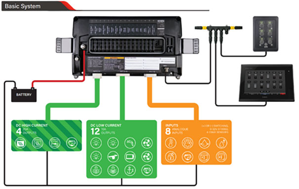
Basic Digital Switching Network:
Basic Rules:
The list below, gives you all the key NMEA 2000 networking rules that, if followed, will ensure your NMEA 2000 network works correctly.
- Network Termination: The network must be properly terminated with a 120-ohm resistor at each end of the backbone cable, never to be installed into tee connectors.
- Power Supply:
- Voltage: The NMEA 2000 supply voltage is designed for a 12V system, usually with devices handling between 9V and 16V DC.
- Current: The total network current draw should be less than 3 amps (60 LEN).
- Device Limit: The network can support a maximum of 50 connected devices.
- Cable Lengths:
- Backbone: The total length of the backbone cable should not exceed 100 meters.
- Drop Cables: Each individual drop cable connecting a device to the backbone should be no more than 6 meters long. The total cumulative length of all drop cables should be less than 78 meters.
- Voltage Drop: The maximum allowable voltage drop across the entire network is typically 1.5V. (Garmin recommendation is 1.67 volts).
NMEA 2000 Network Current :
It’s important to factor in the total current draw. If it exceeds the cable's safe capacity (typically 3A but refer to the manufacturer's specifications for your specific cable type), overheating could occur. Each NMEA 2000 device consumes current from the NMEA network. Current draw on NMEA2000 from a device is measured in LEN and can usually be found the datasheet of the device being installed.
Load Equivalency Number (LEN):
- Every NMEA 2000 certified device has a Load Equivalency Number (LEN), indicating its approximate current draw. 1 LEN = 0.05A (50mA).
- By adding up the LEN values of all connected devices, you can ensure the total network current stays below the recommended limit (typically 60 LEN, which equals 3A).
Power Consumption:
An important consideration of system design and troubleshooting is the power consumption of devices on the NMEA2000 network. Most passive devices, like GPS receivers, fuel flow and level sensors etc will consume power even when the system is not in use. Even if all display devices and engines are shut down, the devices on the network will continue to draw current and transmit data. This is an important consideration when systems have 24-hour circuits and is important to inform your customers that they need to power down their system via the battery switches to ensure the batteries are not drained or have appropriate charging facilities like shore power connections.
NMEA 2000 Network Voltage Drop:
When current flows through the NMEA 2000 network cables, a voltage drop occurs. This means the voltage at the power supply connection point might be slightly higher than the voltage at the farthest device. The longer the backbone cable or the higher the total current draw (LEN), the larger the voltage drop. If the voltage drop exceeds 1.5 volts, data errors can occur.
Calculating Voltage Drop:
Selecting the proper location of the power connection to the NMEA 2000 network depends on the length of the backbone and the power needs of the devices on the network.
To determine the voltage drop in your NMEA 2000 network, use this equation:
Voltage drop = resistance × distance × load × 0.1
- Resistance: Refers to cable resistance (ohms/m). The Garmin cable resistance value is 0.053.
- Distance: Refers to the distance from the power connection to the device located furthest away on the network (in meters).
- Load: Refers to the network load. The network load is the sum of the LEN numbers of all devices from the power connection to the end of the network.
Incorrectly Powered Network:
The diagram below, from Garmin’s NMEA 2000 Fundamentals, shows a simple N2K network with too much voltage drop at one end.
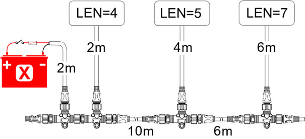
Distance: 2 + 10 + 6 + 6 = 24
LEN: 4 + 5 + 7 = 16
Voltage Drop: 0.053 x 24 x 16 x 0.1 = 2.04 Vdc
Correctly Powered Network:
Garmin suggests fixing this by placing the power insertion point in the middle of the backbone to reduce wire runs.
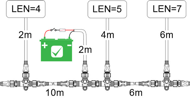
To calculate the new voltage drop, the loads to the left and right of the power supply need to be calculated.
|
Left of power supply: Distance: 2 + 10 + 2 = 14 |
Right of power supply: Distance: 2 + 6 + 6 = 14 |
Each side of the power insertion point can have a voltage drop of up to 1.5 volts independently. The key is that the voltage drop measured from the power insertion point to the furthest device on either side should not exceed 1.5 volts. This means you can have a 1.5-volt drop on one side and a 0-volt drop on the other, or any combination as long as neither side individually exceeds 1.5 volts.
Reducing Voltage Drop:
If the calculated voltage drop is greater than 1.5 volts, you have three main options:
- Move the Power Insertion Point: Move the power insertion point to the middle of the network and as close as possible to the devices consuming the most power.
- Add a Power Insertion Point: Install an additional power cable connected to the same 12V DC supply as the other NMEA 2000 power cables. This injects power closer to the middle of the network, reducing the voltage drop to each end. Each side should be separated with a NMEA 2000 power isolator.
- Use Higher Quality Backbone Cable: NMEA2000 backbone cables are usually thicker gauge wires to reduce voltage drop over long distances. For example, CZone/Ancor backbone cables are special low voltage drop backbone cables. Drop cables are smaller, more flexible cables designed for tight spaces and are lighter to avoid excessive strain on device connection points so these should not be used in place of appropriate backbone cables.
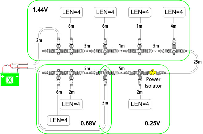
Power Insertion Point Example:
The following diagram shows an example of using a second power insertion point to handle excessive voltage drop. If the power supply was at the end of the network, the total voltage drop would be 8.01V. By adding a second power insertion point in the middle of the lower half of the network, the voltage drop is reduced to 1.44V on the upper half of the network, and 0.68V on the left side of the power insertion point and 0.25V on the right side of the power insertion point.
Termination:
To confirm correct termination on the NMEA 2000 network ( 2 x 120 ohm resistors) you can measure the network resistance. To measure the termination resistance of the NMEA 2000 network and ensure proper operation, you will need a multi-meter capable of measure resistance.
Measuring Termination Resistance:
- Turn off and disconnect all devices from the network.
- Measure the resistance between the CAN_H (high) and CAN_L (low) wires at one end of the network. This will indicate the total termination resistance.
- A properly terminated network with 120 ohm resistors at each end of the network should measure close to 60 ohms.
- If the measured resistance is significantly higher or lower than 60 ohms, the termination resistors may be incorrectly installed, or they may need to be replaced. Locate and measure each terminator and confirm 120-ohm resistance.
- Ensure termination resistors are installed at both ends of the network, using high-quality marine-grade resistors.
- Reconnect the devices and power on the network.
- Verify proper operation of all devices.
Note: Beware of products that have built in termination, for example some masthead wind sensors have built in terminators. In this situation, the masthead device must be treated as the end of the backbone and must not come off a backbone Tee connector.
Best Practices:
- Cable Routing: Carefully plan and route the cables, keeping them away from electrical noise sources and interference. Use appropriate clamps and grommets for secure cable management.
- Grounding: Proper grounding is essential. Ensure all devices are grounded to a common ground point for reliable operation.
- Device Placement: Position devices for easy access during installation, maintenance, and troubleshooting. Avoid areas with direct sunlight or extreme temperatures. Consider access for updating devices and trouble shooting in the future.
- Connector Quality: Use high-quality, marine-grade connectors. Ensure proper installation and secure fastening.
- Termination: Proper termination is critical. Use the correct termination resistors and install them at both ends of the network bus.
- Device Compatibility: Verify that all devices are compatible with the NMEA2000 protocol. Consult manufacturer specifications and compatibility lists.
- Device NMEA 2000 Sentences: Each manufacturer will list the NMEA2000 sentences that the device can transmit and receive. This is important to understand when you want to use NMEA2000 functionality, like the Dometic Trim tab adaptive functionality.
- Maintenance: Perform regular maintenance. Inspect cables, connectors, and devices for wear or damage. Update device firmware as needed.
- Documentation: Keep detailed documentation of the network installation, including cable routing, connector locations, termination points, and even labelling schemes. This will be invaluable for future maintenance and troubleshooting.
- Power Supply Capacity: Choose a clean power supply with sufficient capacity to handle the total current draw (LEN) of all connected devices and other loads on the circuit.
Following these best practices will ensure a reliable NMEA2000 network with minimal downtime.
Troubleshooting:
When encountering issues with your NMEA2000 network, follow these steps to diagnose and resolve the problem. Remember, some checks are simpler and quicker to perform than others.
Start with the basics:
- Verify Power & Ground: Use a voltmeter to confirm all devices are receiving power and ground.
- Check Termination: Ensure proper installation of termination resistors at both network ends. Measure network resistance to ensure correct termination.
- Inspect Physical Connections: Look for damage, corrosion, or loose connections. Re-seat and clean connections if necessary.
- Verify Device Instances: With an MFD or NMEA 2000 diagnostic tool, verify devices do not have conflicting instances. For example, two fuel slow sensors, or two fuel level sensors usually require the instances to be manually set.
- Isolate Faulty Devices: Disconnect devices one by one to see if the network recovers. A device causing the network to function properly upon disconnection might be faulty.
- Device Firmware: Ensure all devices have the latest firmware. Check manufacturer websites for updates and upgrade devices as needed.
Advanced Troubleshooting:
- Error Messages: Use a diagnostic tool to check for error messages on the network. These messages can indicate specific device or network issues.
- Network Load: Use a diagnostic tool to inspect the network traffic load. Generally, it's recommended to maintain the network load below a certain threshold (often around 80%) to avoid compromising communication performance.
Error messages and network load can usually be displayed on a MDF (Multi-Function Display) found under network diagnostics or network settings.
Electrical Noise:
For advanced users, a scope can be used to identify electrical noise on the bus. If noise is present, take steps to eliminate or reduce it.
Network Configuration:
Verify the network configuration is correct. Common issues that occur are when troubleshooting engine specific data issue like fuel flow and engine battery voltage is the vessel setup within the MFD itself. In the network settings of the MFD, ensure the following settings are configured:
- Number of engines
- Number of tanks
- Fluid type and tank capacities
- Fuel remaining source
- Engine instances correctly assigned: 0 for Port and 1 for Starboard.
- Sources are correctly assigned in network settings, usually an Auto Select will correctly assign the right devices after the vessel set up is configured correctly.